
L40, Rain Sensor
- Admin

- Apr 15, 2020
- 1 min read
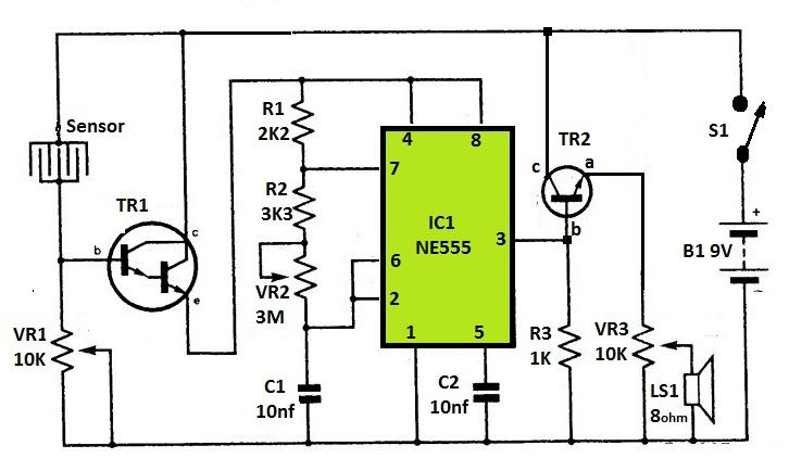
It’s the circuit diagram ofa simple rain sensor with the feature of pitch and volume controls in the alarm signal. Whenever the sensor is contact by droplets of water, the Darlington transistor TR1 will conduct. This enables goes on IC1, a 555 Astable multi-vibrator tone generator, to function, powering a small loud-speaker through a driver transistor (TR2). VR2 determines the pitch of the audio tone, which can be anything from about 25 Hz to 18 kHz, while VR3 is used for adjusts the volume of the speaker. You can adjust the sensitivity of the circuit by VR1. The Darlington pair could be constructed with two separate ZTX300s or a single TlP122. For the sensor, use a small piece of stripboard, linking alternate strips into an interlocking design.
Components-
IC1 = NE555
TR1 = TIP122
TR2 = BFY51
R1 = 2K2, R3 = 3K3, R3 = 1K
VR1 = 10K, VR2 = 3M, VR3 = 10K
C1 = 10nf, C2 = 10nf
Loud Speaker LS1 = 8 ohm
9volt Battery


Comments