
L45, 3 LED Battery Moniter
- Admin

- Apr 16, 2020
- 1 min read
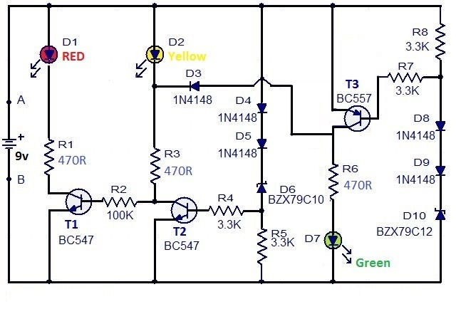
This is the circuit diagram of a 3 LED bar graph type battery monitor circuit that is ideal for monitoring the voltage level of an automobile battery. When battery voltage is 11.5V or less transistor Q1 will be On and the LED D1 will be glowing. When battery voltage is between 11.5 and 13.5V, the transistor Q2 will be On and the LED D2 will be glowing. When battery voltage is above 13.5V the transistor Q3 will be On and the LED D7 will be glowing.
Components-
Transistor Q1-Q2 = BC547, Q3 = BC557
R1 = R3 = R6 = 1K, R2 = 100K
R4 = R5 = R7 = R8 = 3.3K
D1 = D2 = D7 = LEDs (Red, yellow & Green)
D3 = D4 = D5 = D8 = D9 = 1N4148
D6 = D10 = BZX79C10
Battery 9v
For circuit protection as witch (on/off) can use in series with battery.


Comments